

Sizing and Wiring DC Isolator Switches and Battery Disconnects for Solar PV Systems
Direct current (DC) arcs do not naturally extinguish like alternating current (AC) waveforms, which pass through zero volts 120 times every second. In photovoltaic strings running between 300V and 600V DC, or high-capacity 48V battery banks pushing 150 to 300 continuous amperes, opening an unrated mechanical switch under load creates a sustained plasma arc hot enough to weld brass contacts, vaporize terminal blocks, and trigger catastrophic electrical fires. Sizing and wiring DC disconnects (isolators) requires matching thermal ampacity while evaluating the physical breaking mechanisms of direct current under full operational stress.
Under National Electrical Code (NEC) Article 690 (Solar Photovoltaic Systems) and Article 705 (Interconnected Power Production), dedicated DC disconnects provide mandatory isolation boundaries for emergency personnel and maintenance technicians. Properly sizing the conductors entering and exiting these switches requires applying the standard 156% continuous duty and irradiancy multiplier ($I_{sc} times 1.56$), verifying 75°C terminal lug temperature limits, and selecting true load-break switches capable of handling continuous direct-current interruption.
Calculating Solar DC Wire Size & Voltage Drop?
Input your string voltage, short-circuit current (Isc), one-way distance, and allowable voltage drop to compute the exact AWG gauge needed.
In This Guide:
- NEC 690.13 & 690.15: Mandated DC Disconnect Locations & Clearances
- The Physics of DC Arc Extinction: Why AC Switches Fail Catastrophically
- Sizing Conductors for DC Isolators (The 1.56 Multiplier & 75°C Lugs)
- 48V Battery Disconnect Switches: Inrush, AIC, and Continuous Sizing
- DC Isolator Switch Sizing & Terminal Specifications Table
- Frequently Asked Questions
NEC 690.13 & 690.15: Mandated DC Disconnect Locations & Clearances
Under NEC Section 690.13, a photovoltaic system disconnecting means must be installed at a readily accessible location either on the outside of the building or inside nearest the point of entrance of the system conductors. The switch must isolate all ungrounded DC conductors from all other conductors in the building.
Key code mandates for DC isolators include:
- Readily Accessible: The switch handle must be operable without requiring portable ladders, climbing over obstacles, or removing panel covers. In residential dwellings, the center of the handle grip cannot exceed 6 feet 7 inches (2.0 m) above finished grade or the working platform (NEC 240.24).
- Working Clearances: In accordance with NEC Table 110.26(A)(1), disconnect switches operating up to 600V nominal must maintain a minimum clear working space depth of 3 feet (36 inches) in front of the enclosure, with a width of 30 inches or the width of the equipment (whichever is greater).
- Grouping & Identification: Every PV disconnect must be marked with a permanent, UV-resistant engraved label stating: “PHOTOVOLTAIC SYSTEM DC DISCONNECT”, along with ratings for Maximum System Voltage ($V_{oc}$ cold) and Maximum Circuit Current ($I_{sc} times 1.25$).

The Physics of DC Arc Extinction: Why AC Switches Fail Catastrophically
One of the most dangerous installation errors in renewable energy systems is using an AC-rated knife switch, safety switch, or molded-case circuit breaker in a DC circuit. The electrical physics of breaking AC versus DC current are fundamentally different:
- AC Zero-Crossing: Alternating current alternates polarity, dropping voltage and current to absolute zero twice per cycle (every 8.33 milliseconds in a 60Hz system). As switch contacts pull apart, this zero-crossing naturally quenches the air ionization, extinguishing the electrical arc with minimal contact erosion.
- DC Continuous Potential: Direct current delivers constant, non-zero potential. When mechanical contacts open under 400V or 48V DC, current ionizes the air gap, establishing a plasma channel that sustains itself across opening distances exceeding several inches. Without specialized suppression, the arc burns continuously until the metal switch housing melts or an explosive phase-to-ground flashover occurs.
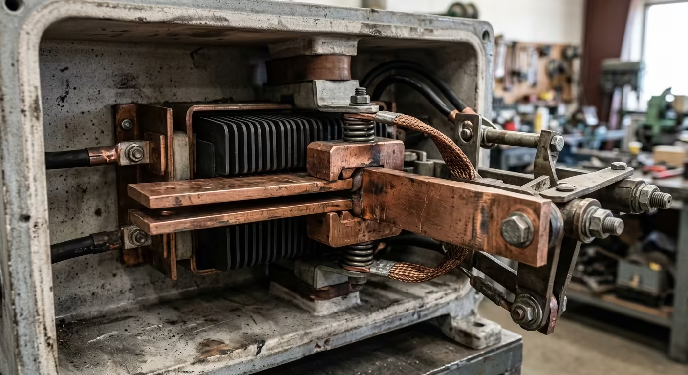
True DC disconnect switches incorporate magnetic blowout coils that generate a perpendicular magnetic field, forcing the arc outwards away from the contacts and driving it into a series of ceramic arc chutes. These chutes split, cool, and stretch the plasma arc until the voltage drop across the gap exceeds the system potential, forcing the circuit open safely.
Sizing Conductors for DC Isolators (The 1.56 Multiplier & 75°C Lugs)
When sizing conductors routing through an exterior DC isolator, the conductor must satisfy two separate criteria under NEC Section 690.8:
- Continuous Duty & Overcurrent Sizing: Conductor allowable ampacity (before deratings) must be sized at 125% of the Maximum Circuit Current, which is already 125% of the array short-circuit current ($I_{sc}$):
Minimum Ampacity = Isc × 1.25 × 1.25 = Isc × 1.56 - Terminal Temperature Limitations (NEC 110.14(C)): Even if you pull 90°C insulated wire (such as XLPE PV Wire or THHN/THWN-2), mechanical screw terminals inside commercial disconnect switches are almost universally rated for 75°C. You must verify that your final ampacity after temperature corrections does not exceed the 75°C column of NEC Table 310.16.
For example, if two parallel strings of solar panels combine before an isolator with a total $I_{sc}$ of 26.0A, the switch and conductors must be rated for at least $26.0text{A} times 1.56 = 40.56text{ Amps}$. A 8 AWG copper conductor (rated for 50A at 75°C) satisfies both continuous load criteria and terminal rating bounds.
48V Battery Disconnect Switches: Inrush, AIC, and Continuous Sizing
In low-voltage, high-power battery storage (48V nominal systems supporting 6kW to 15kW inverters), disconnect sizing rules reverse: voltage is low, but amperage is enormous.
When selecting a battery master disconnect (such as an industrial Blue Sea 300A/600A HD switch):
- Continuous Current vs. Cranking Ratings: Marine switches often advertise attractive “cranking” or “intermittent” ratings (e.g., 1000A for 30 seconds). You must size strictly by the Continuous Rating (typically 300A, 500A, or 600A continuous). A 12kW continuous inverter operating at a 44V low-battery cutoff draws up to 300 continuous amps ($12,000text{W} / (44text{V} times 0.91) = 300text{A}$), demanding a switch rated for at least 350A continuous duty.
- AIC and Catastrophic Fault Clearing: A mechanical battery switch is not an overcurrent protection device. Under a dead-short condition, a large lithium bank discharges thousands of amperes. The battery disconnect must be backed immediately by an in-line Class T catastrophic fuse with a 20,000A Ampere Interrupting Capacity (AIC) located within 12 to 18 inches of the positive battery terminal.
- Pre-Charge Resistor Bypass: Large hybrid inverters contain massive input capacitor banks. Turning a battery disconnect switch directly onto a discharged inverter creates a momentary 1,000+ amp inrush spike that pits switch contacts and trips BMS circuit boards. Use a pre-charge circuit with an in-line 25W to 50W resistor (around 30 ohms) for 5 seconds prior to engaging the main disconnect.
DC Isolator Switch Sizing & Terminal Specifications Table
The table below provides engineering sizing specifications for common residential solar string and battery storage disconnect configurations:
| Application Circuit | Max Operating Limits | Min. Switch DC Rating | Min. Conductor Size | Terminal Stud / Lug Torque |
|---|---|---|---|---|
| Single High-Voltage String | 500V DC / 13.5A Isc | 600V DC / 25A Load-Break | 10 AWG Copper (75°C) | 18–20 in-lbs (Screw) |
| Dual String Combiner Output | 500V DC / 27.0A Isc | 600V DC / 45A Load-Break | 8 AWG Copper (75°C) | 25–30 in-lbs (Screw) |
| 48V 6kW Inverter Battery Run | 48V DC / 160A Peak Cont. | 48V–64V DC / 300A Cont. | 2/0 AWG Class K Copper | 120–140 in-lbs (3/8″ Stud) |
| 48V 12kW Inverter Battery Run | 48V DC / 300A Peak Cont. | 48V–64V DC / 500A Cont. | 4/0 AWG or 2× 2/0 AWG | 140–160 in-lbs (1/2″ Stud) |
Frequently Asked Questions
Q: Can I use a standard 240V AC safety switch or breaker for my solar DC circuit?
A: No. Standard AC disconnect switches and circuit breakers rely on zero-crossing AC waveforms to clear electrical arcs. Under 400V to 600V direct current, an AC switch cannot extinguish the continuous plasma arc, causing contacts to weld together and resulting in catastrophic enclosure fires.
Q: What is the difference between a load-break and non-load-break DC isolator?
A: A load-break isolator is mechanically certified to break full operational current safely without damaging internal contacts. A non-load-break isolator is an isolation-only switch designed for servicing; it must only be operated after the inverter has been shut down and current draw has dropped to zero.
Q: Where must the rooftop solar DC disconnect switch be mounted?
A: Under NEC 690.13, the main PV disconnect must be located in a readily accessible position either outside the building or inside nearest the point where DC conductors enter the structure. In addition, rapid shutdown initiators must be clearly marked and accessible at the service entrance.
Q: Why do DC isolator terminals require calibrated torque verification?
A: Loose mechanical terminations create localized contact resistance. At high currents, even a fractional-ohm resistance generates severe thermal heat ($P = I^2 R$), which degrades terminal insulation, melts plastic switch housings, and leads to direct series arc faults.
Securing Your Electrical Conduits & Cables?
Keep your electrical installations neat and code-compliant. Check out our parametric conduit clamps and cable organizers, custom-engineered and 3D printed in rugged industrial PETG.
