

Sizing Battery Cables for 48V Off-Grid Solar Storage (Inverter to Busbar)
Modern off-grid and hybrid solar power systems rely on 48-volt nominal battery architectures to support whole-home electrical loads. By stepping nominal battery voltage up from 12V or 24V to 48V, system amperage drops by 75% for the same watt output, allowing for significantly more manageable conductor gauges. However, running a 5,000-watt to 12,000-watt inverter off a 48V battery bank still commands massive continuous and surge currents that challenge typical electrical wiring standards.
Unlike alternating current (AC) residential branch circuits, low-voltage direct current (DC) battery loops cannot tolerate standard allowable voltage drops. Sizing the primary conductors between your server-rack lithium iron phosphate (LiFePO4) batteries, positive and negative distribution busbars, and the inverter requires evaluating continuous continuous thermal limits, surge discharge ratings, short-circuit fault currents (AIC), and conductor flexibility.
Calculate Solar & Battery Conductor Sizes
Input your inverter wattage, DC operating voltage, cable length, and permissible voltage drop to calculate required AWG gauge and circular mils.
In This Guide:
- 48V Inverter Current Math: Low-Voltage Cutoff & Inverter Efficiency
- Voltage Drop Limits in 48V Storage: Why 1% is the True Ceiling
- 48V Battery & Inverter Cable Sizing Reference Matrix
- Conductor Type: Class K Welding Cable vs. THHN Building Wire
- Catastrophic Overcurrent Protection: Why Class T Fuses are Mandatory
- Frequently Asked Questions
48V Inverter Current Math: Low-Voltage Cutoff & Inverter Efficiency
The most common design failure when sizing battery cables is calculating DC current using nominal voltage (48.0V) and theoretical 100% conversion efficiency. In practice, power conversion involves losses, and battery voltages sag under load.
To establish the true continuous current demands of an off-grid inverter, you must apply the full electrical engineering equation:
Continuous DC Current (I) = Continuous AC Wattage / (Low-Voltage Cutoff × Inverter Efficiency)
Consider a standard 6,000-watt off-grid inverter (such as an EG4 6000XP, Victron MultiPlus-II, or Sol-Ark 12K operating at 6kW output):
- Inverter Output: 6,000 Watts
- Inverter Efficiency: ~93% (0.93) at heavy load
- Low-Voltage Disconnect Threshold: 42.0V to 44.0V (the point where a depleted LiFePO4 bank triggers inverter shutdown)
Calculating using real-world minimum voltage reveals the true continuous draw:
I = 6,000W / (44.0V × 0.93) = 6,000W / 40.92V = 146.6 Amps Continuous
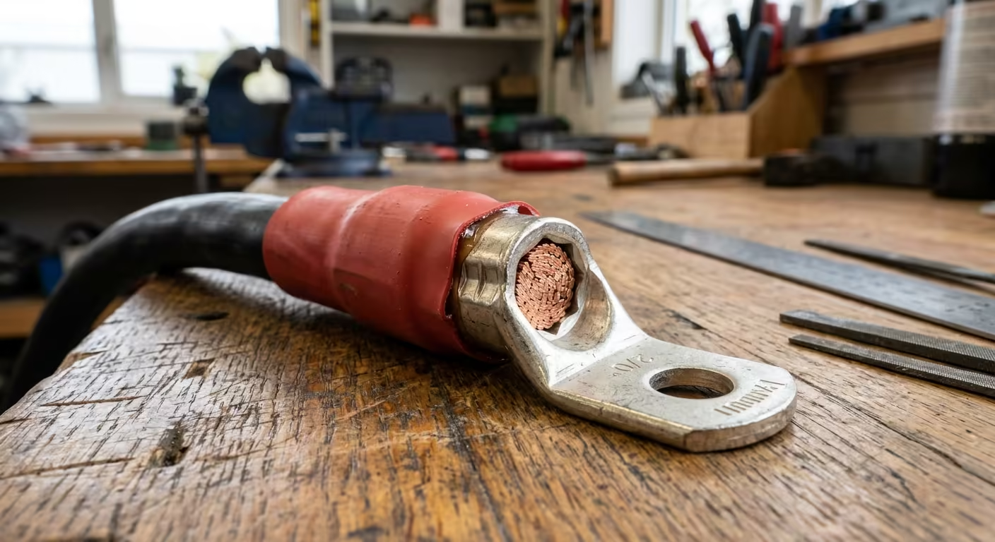
In accordance with NEC Section 690.8 and Article 705, continuous circuits must incorporate a 125% continuous duty margin: $146.6text{A} times 1.25 = 183.3text{ Amps}$. Therefore, a 6,000W inverter requires a conductor and overcurrent protection device rated for a minimum of 200 Amps, necessitating 2/0 AWG copper cable rather than marginal 1/0 or 2 AWG conductors.
Voltage Drop Limits in 48V Storage: Why 1% is the True Ceiling
While the National Electrical Code permits up to a 3% voltage drop across standard branch circuits, a 3% loss on a 48V battery bank is unacceptable in high-performance solar engineering. On a 48V system, a 3% drop equals a 1.44-volt loss between the battery terminals and the inverter.
In lithium storage systems, that 1.44V loss creates severe operational issues:
- Premature Low-Voltage Cutoff: The inverter senses 43.5V and trips offline while the actual battery cells are still sitting at 45.0V with 15% to 20% remaining state-of-charge (SoC).
- Pure Resistive Heat Losses: At 150 amps, losing 1.44 volts equates to $150text{A} times 1.44text{V} = 216text{ Watts}$ of energy continuously dissipated as thermal heat within the cable conduit and enclosures.
- BMS Inbalance Faults: In parallel battery setups, cables of unequal length or high resistance cause current hogging, where one battery module discharges or recharges significantly faster than its neighbours.
For these reasons, professional solar installations enforce a maximum voltage drop ceiling of 1.0% (0.48V maximum drop) across the entire battery-to-inverter loop.
48V Battery & Inverter Cable Sizing Reference Matrix
The table below outlines code-compliant copper conductor sizes, circular mil areas, and maximum recommended one-way circuit lengths to maintain less than 1.0% voltage drop under full continuous inverter load:
| Inverter Continuous Size | Max Continuous Draw (44V) | Min. Conductor (90°C) | Max One-Way Length (<1% Drop) | Recommended Class T Fuse |
|---|---|---|---|---|
| 3,000 Watts | 75 Amps | 2 AWG (66,360 CM) | 16 Feet | 100A / 125A |
| 5,000 Watts | 125 Amps | 1/0 AWG (105,600 CM) | 15 Feet | 175A / 200A |
| 6,500 Watts | 160 Amps | 2/0 AWG (133,100 CM) | 15 Feet | 225A / 250A |
| 8,000 Watts | 200 Amps | 4/0 AWG (211,600 CM) | 18 Feet | 300A / 350A |
| 12,000 Watts | 300 Amps | Parallel 2× 2/0 AWG or 2× 4/0 AWG | 15 Feet | 400A (Dual Feeds) |
Conductor Type: Class K Welding Cable vs. THHN Building Wire
Using standard solid or coarse Class B stranded building wire (such as standard building-supply THHN/THWN) for primary battery interconnects is a major installation error:
- Coarse Stranding Mechanical Stress: A 4/0 AWG Class B THHN cable contains only 19 rigid copper strands. Forcing this stiff cable into compact battery boxes exerts massive leverage and rotational torque on the battery terminal posts, regularly cracking internal BMS circuit boards and loosening bolted joints over time.
- Flexible Fine-Strand Conductors: High-quality battery banks should use UL-listed Class K or Class M flexible stranded cable (often marketed as UL 1277 or UL 1426 Marine/Battery Cable). A 4/0 AWG Class K conductor contains over 2,100 fine copper micro-strands. This provides flexibility, absorbs thermal movement, and eliminates mechanical strain on the battery casing.
- Ferrule & Lug Termination Rule: Fine-strand cables cannot be secured directly under standard set-screw lugs. The screw cuts and shears the delicate micro-strands, creating a localized high-resistance failure point. You must terminate fine-strand cable into a heavy copper closed-end compression terminal using a calibrated hydraulic hex crimper.
Catastrophic Overcurrent Protection: Why Class T Fuses are Mandatory
Lithium iron phosphate (LiFePO4) battery modules exhibit exceptionally low internal electrical resistance. In the event of a dead short across your inverter’s DC input terminals, a 48V bank of 4 or 6 rack-mounted batteries can discharge in excess of 10,000 to 20,000 Amps in milliseconds.
Standard automotive or marine fuses are incapable of clearing this scale of fault current:
- ANL and Mega Fuses Fail: Typical ANL or Mega fuses have an Ampere Interrupting Capacity (AIC) of only 2,000A to 6,000A at 48V DC. Under a direct short on a lithium bank, an ANL fuse can vaporize, sustained arcs jump across the blown gap, and the fuse housing explodes, resulting in catastrophic electrical fire.
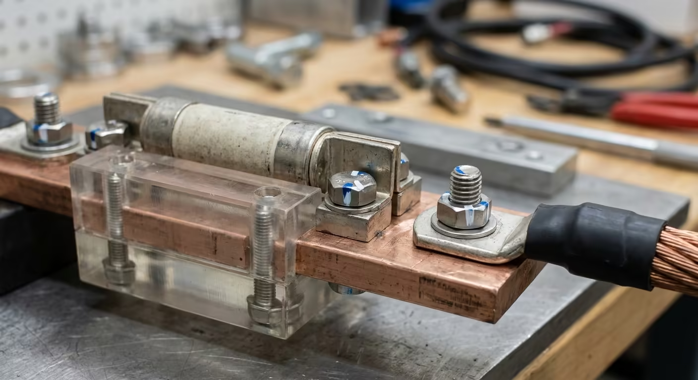
- Class T Fuses are Engineered for Lithium: Class T fast-acting current-limiting fuses carry a verified 20,000 Amp AIC rating at 125V DC. Under an extreme short, a Class T fuse clears the circuit within milliseconds, safely quenching the plasma arc inside an industrial silica sand chamber.
Install the Class T fuse on the ungrounded (positive) conductor as close as physically possible to the battery or distribution busbar, never exceeding 12 to 18 inches of unfused conductor length.
Frequently Asked Questions
Q: Can I use car audio 0-gauge (1/0) wire for my 48V solar inverter?
A: No. Cheap car audio wire is often manufactured using Copper-Clad Aluminum (CCA) rather than Oxygen-Free Pure Copper (OFC). CCA exhibits 39% higher electrical resistance than copper and oxidizes rapidly under continuous load. Always verify the cable is stamped as 100% pure annealed electrolytic copper.
Q: Why do battery cables need to be exactly the same length in parallel banks?
A: DC current takes the path of least resistance. If one battery has 2 feet of cable to the main busbar and a second has 4 feet, the first battery will supply and absorb nearly 60% of the total current. Equal-length, matched-gauge cables are essential for keeping parallel battery modules balanced.
Q: What torque spec should be applied to battery ring terminal bolts?
A: Over-tightening strips soft aluminum battery terminals, while under-tightening causes high contact resistance and burned lugs. Most M8 terminal bolts on lithium modules require 8 to 10 Newton-meters (70 to 88 inch-pounds) of torque, verified with a calibrated torque wrench.
Q: Do I need to fuse both the positive and negative battery cables?
A: No. Under NEC 240 and 690 guidelines, overcurrent protection is installed exclusively on the ungrounded conductor (the positive rail). Fusing the negative conductor is dangerous because if the negative fuse blows while the positive remains connected, the entire chassis and ground plane can become energized at full battery potential.
Securing Your Electrical Conduits & Cables?
Keep your electrical installations neat and code-compliant. Check out our parametric conduit clamps and cable organizers, custom-engineered and 3D printed in rugged industrial PETG.
