

Wire Sizing for Marine & RV DC-to-AC Inverters (1000W to 3000W)
Inverters are the heart of any modern off-grid marine or RV electrical system, seamlessly converting 12V or 24V direct current (DC) from a battery bank into 120V alternating current (AC) to run household appliances like microwaves, coffee makers, and air conditioners. However, stepping low-voltage DC up to high-voltage AC demands an enormous amount of continuous electrical current. A 3000W inverter operating at peak capacity on a 12V system routinely pulls in excess of 300 amps.
Pushing 300 amps through undersized cables creates extreme thermal resistance, bleeding battery capacity away as wasted heat and inducing severe voltage drop. If the voltage plunges below the inverter’s low-voltage cutoff threshold, the unit will shut down completely—even if your batteries are fully charged. Properly sizing inverter conductors requires mastering the true DC amp draw formula, understanding ABYC E-11 voltage drop limits, and strictly utilizing Class K tinned copper marine cable.
Need Exact Wire Sizing for Your DC Run?
Input your inverter’s maximum continuous amperage, total round-trip distance, and target voltage drop to calculate the exact ABYC-compliant AWG.
In This Guide:
The True DC Amp Draw Formula (Accounting for Efficiency)
The most common mistake DIYers make when sizing inverter wire is calculating amperage based on nominal voltage and 100% conversion efficiency. To find the maximum continuous DC current, you must account for the inverter’s efficiency loss (typically 85% to 90%) and the lowest voltage the battery will reach before the system shuts off (usually 11.0V to 11.5V on a 12V bank).
Continuous DC Amps = AC Watts / (Low Voltage Cutoff × Inverter Efficiency)
Example Calculation: A 2000W inverter operating on a 12V battery bank with an 85% efficiency rating and an 11.0V low-voltage cutoff limit.
Amps = 2000W / (11.0V × 0.85)Amps = 2000W / 9.35V = 213.9 Amps
While standard Ohm’s law ($2000text{W} / 12text{V}$) suggests a 166-amp draw, the real-world maximum continuous load is actually 214 Amps. Sizing your cables for 166A instead of 214A guarantees severe overheating and catastrophic voltage drop under heavy load.
ABYC Voltage Drop Limits (The 3% vs 10% Rule)
Under ABYC E-11 standards, an inverter is technically classified as a “non-critical” circuit, allowing for a 10% voltage drop. However, allowing a 10% drop (1.2V on a 12V system) is highly detrimental to an inverter. If your battery rests at 12.2V and you lose 1.2V to wire resistance, the inverter sees 11.0V at its input terminals and will trigger a low-voltage alarm, shutting down your 120V AC appliances.
For this reason, professional marine electricians size all primary inverter feed cables to a strict 3% maximum voltage drop (just 0.36V of allowable loss).
To calculate the required Circular Mils (CM) for a 3% drop, use the standard DC formula, ensuring distance ($L$) represents the Total Round-Trip of both the positive and negative cables:
CM = (10.75 × I × L) / 0.36V
Overcurrent Protection: Why Class T Fuses are Mandatory
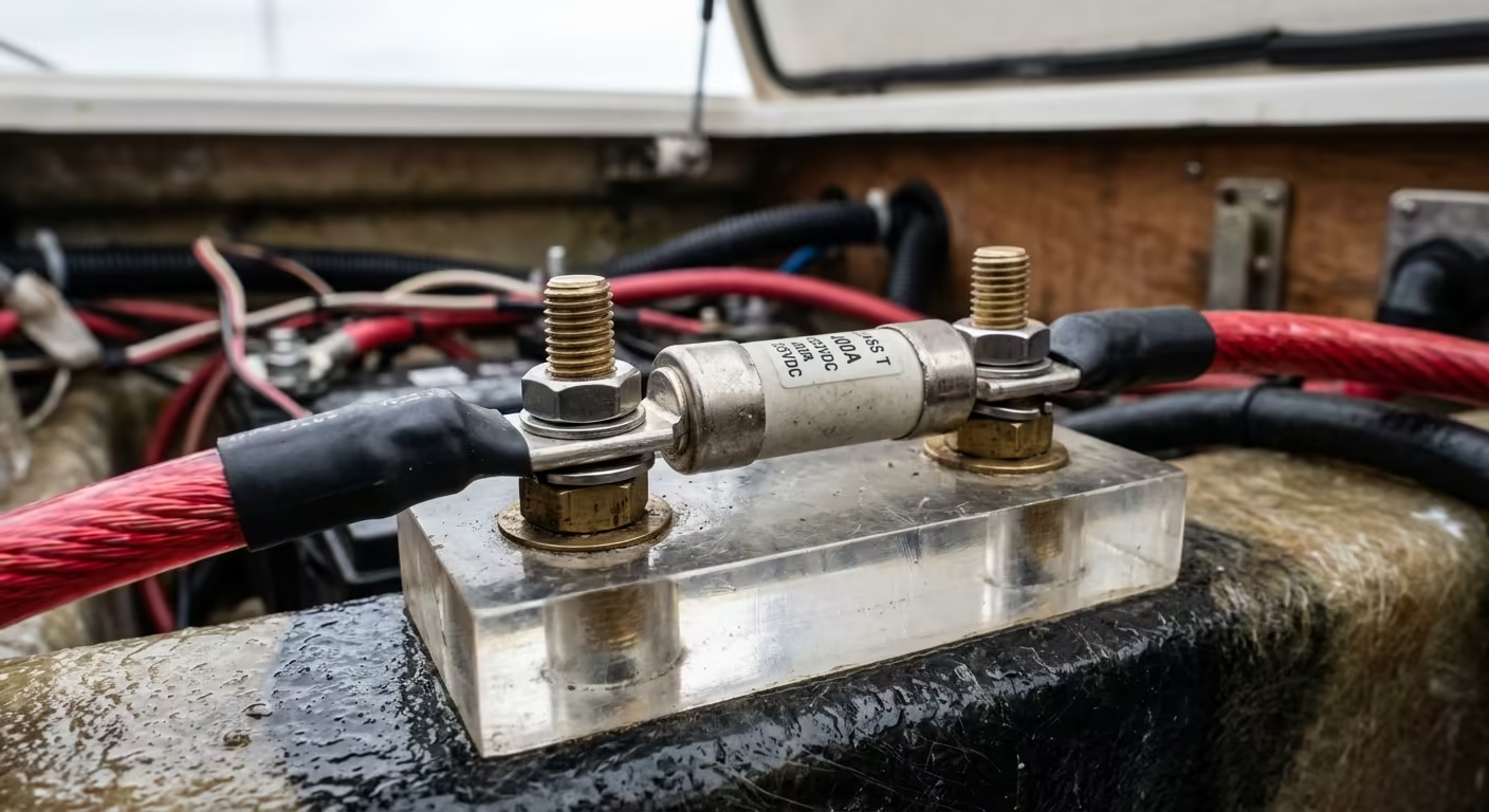
If you are pairing your high-power inverter with a modern Lithium Iron Phosphate (LiFePO4) battery bank, standard ANL or Mega fuses are no longer sufficient. Lithium batteries have incredibly low internal resistance. In the event of a dead short across your inverter’s DC input, a lithium bank can discharge upwards of 10,000 to 20,000 amps in milliseconds.
Standard ANL fuses have an Ampere Interrupting Capacity (AIC) of only 2,000A to 6,000A. A dead short can cause an ANL fuse to vaporize and arc across the gap, starting a fire. You must install a Class T catastrophic fuse, which is engineered with a 20,000A AIC rating, mounted within 7 inches of the battery’s positive terminal.
12V & 24V Inverter Cable Sizing Matrix
The table below provides the minimum recommended UL 1426 Tinned Copper AWG sizes targeting a strict 3% voltage drop. (Distances listed are One-Way from battery to inverter; the math natively accounts for the round trip).
| Inverter Size / Voltage | Real Max DC Amps | 5 ft One-Way Run | 10 ft One-Way Run | Recommended Fuse |
|---|---|---|---|---|
| 1000W (12V DC) | 107 Amps | 2 AWG | 1/0 AWG | 150A |
| 2000W (12V DC) | 214 Amps | 1/0 AWG | 3/0 AWG | 300A |
| 3000W (12V DC) | 321 Amps | 3/0 AWG | Parallel 2× 2/0 AWG | 400A |
| 2000W (24V DC) | 107 Amps | 4 AWG | 2 AWG | 150A |
| 3000W (24V DC) | 160 Amps | 2 AWG | 1/0 AWG | 200A |
*Note: A 3000W load at 12V is notoriously difficult to cable. Transitioning to a 24V battery bank cuts the required amperage in half, allowing you to use dramatically thinner, cheaper, and more flexible 1/0 AWG cable instead of wrestling with dual 2/0 AWG runs.
Frequently Asked Questions
Q: Can I use standard automotive jumper cables to wire my inverter?
A: No. Automotive cables are usually made of bare copper or copper-clad aluminum (CCA). Bare copper oxidizes rapidly in marine environments, increasing electrical resistance. You must use UL 1426 Marine Grade Tinned Copper wire (Class K stranding), which resists saltwater corrosion and hull vibration.
Q: Do I need to fuse both the positive and negative inverter cables?
A: No. Under ABYC standards, overcurrent protection is installed exclusively on the ungrounded conductor (the positive cable). Fusing the negative conductor can create a dangerous condition where the negative fuse blows, but the chassis and circuits remain energized at full battery potential.
Q: How do I terminate massive 4/0 AWG cables at the inverter?
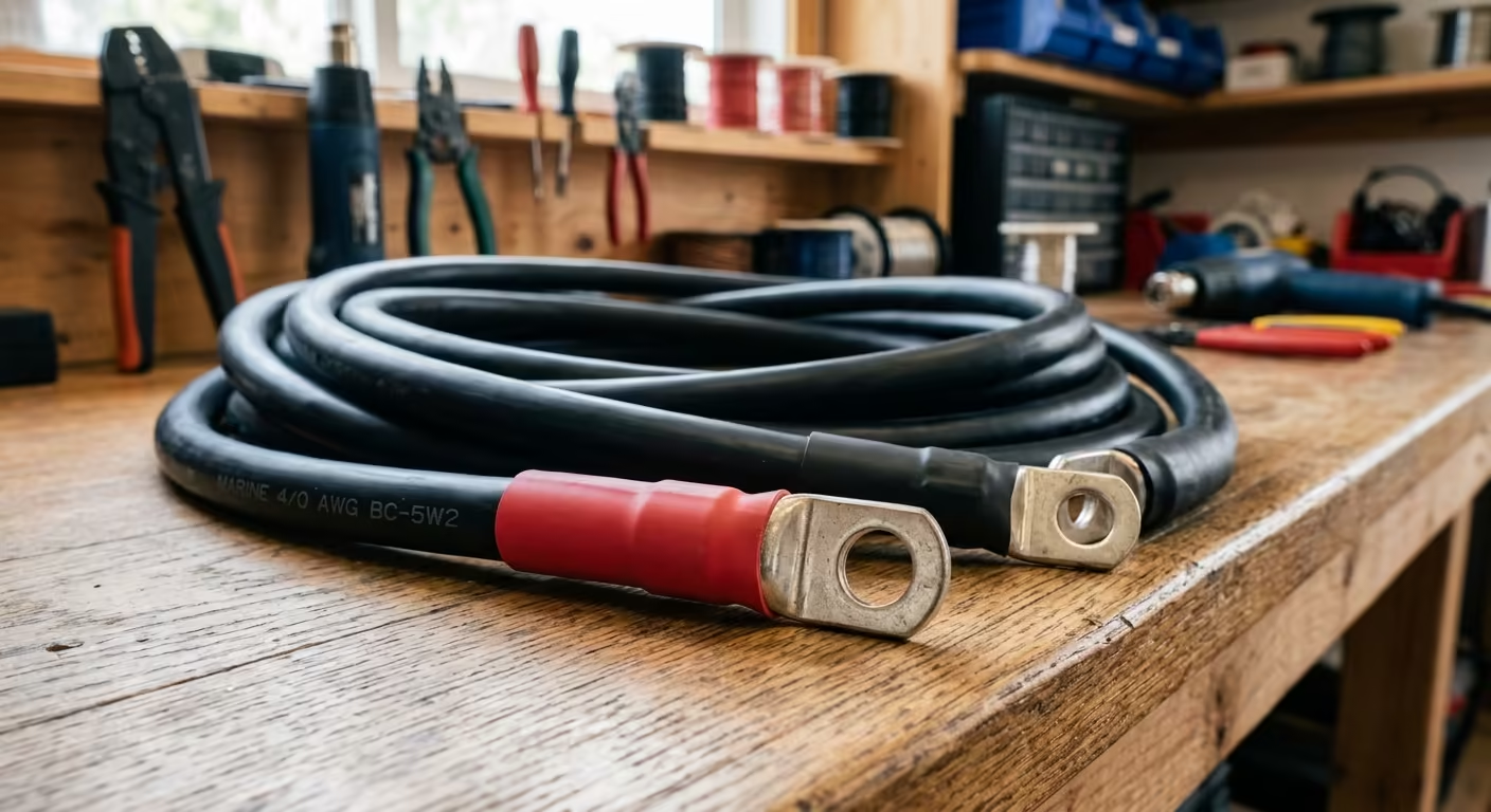
A: Fine-strand Class K marine wire cannot be clamped directly under set screws without breaking the strands. You must use a calibrated hydraulic hex crimping tool to compress heavy-duty tinned copper closed-end ring lugs onto the cable, sealed with adhesive-lined marine heat shrink.
Securing Your Marine Cables?
Keep your hull wiring neat, secure, and ABYC compliant. Check out our parametric conduit clamps and marine cable organizers, custom-engineered and 3D printed in rugged industrial PETG.
