
Alternator to House Battery DC-DC Charger Wire Sizing (40A–60A)
Charging an auxiliary lithium (LiFePO4) or AGM battery bank directly from an engine alternator is the foundation of off-grid electrical independence in campervans, expedition rigs, and cruising boats. However, lithium chemistries exhibit exceptionally low internal electrical resistance. If connected directly across an alternator using a traditional mechanical split-charge relay or solenoid, a depleted lithium bank will pull peak continuous amperage, rapidly overheating and destroying standard vehicle alternators at idle. A dedicated DC-to-DC charger (battery-to-battery or B2B charger) resolves this by regulating the charging current and stepping up voltage to match custom absorption profiles.
While a DC-DC charger protects the alternator, delivering 40A to 60A of continuous direct current across extended vehicle lengths presents severe thermal and electrical challenges. Because the charger is frequently installed 15 to 30 feet away from the engine bay in the rear living quarters or battery locker, conductor resistance leads to substantial voltage drop. Sizing the primary input and output wiring requires accounting for charger conversion efficiency, calculating true round-trip circuit length, and complying with ABYC E-11 marine and automotive electrical standards.
Calculating DC Feeder & Battery Runs?
Eliminate dangerous voltage drop and undersized conductor hazards for your mobile, marine, and RV branch circuits.
In This Guide:
The Efficiency Gap: Why Input Amps Exceed Output Amps
The single most frequent mistake made when sizing DC-DC charger wiring is calculating wire gauge based solely on the charger’s advertised output rating. A charger rated for 60 amps pushes 60 amps into the house battery, but it requires significantly more amperage on its input side to do so.
DC-DC buck-boost converters operate at roughly 88% to 92% electrical efficiency. Furthermore, they frequently boost a sagging alternator input voltage (such as 12.8V) up to a lithium bulk charge voltage of 14.4V. Consider the mathematical power balance for a 60A unit:
- Output Power Demand: 60 Amps × 14.4 Volts = 864 Watts
- Input Power Required (at 90% Efficiency): 864 Watts / 0.90 = 960 Watts
- Actual Input Amperage Draw (at 12.8V Input): 960 Watts / 12.8 Volts = 75 Amps
In this common operating scenario, your alternator feeder cable is carrying 75 amps of continuous current, not 60 amps. Sizing the input circuit for 60 amps creates an immediate thermal bottleneck, causing high voltage drop that triggers the charger’s low-voltage cut-off setting.
Dedicated Negative Return Cable vs. Vehicle Chassis Ground
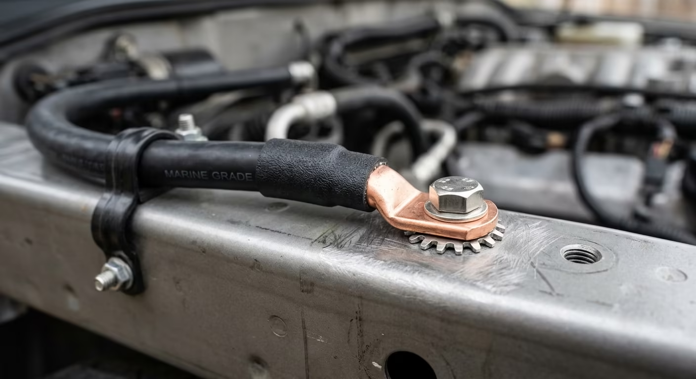
In marine applications, ABYC E-11 strictly prohibits using the boat’s hull or metallic framework as a current-carrying conductor. Every circuit must utilize a fully insulated negative return wire sized identically to the positive conductor.
In campervans and commercial vans, builders frequently attempt to save money by terminating the charger negative directly to the nearest steel chassis rib. While the vehicle chassis is technically grounded to the starter battery, modern unibody vans consist of stamped steel panels held together by structural adhesives and spot welds. Steel has roughly five times higher electrical resistivity than copper.
Wire Sizing Tables: 40A, 50A, and 60A DC-DC Chargers
In 12V DC electrical circuits, circuit length is always calculated as round-trip distance (the total length of the positive conductor from the starter battery to the charger, plus the negative conductor back to the battery). Conductor sizes below are calculated to maintain total voltage drop strictly under the critical 3% ABYC threshold (0.36V drop at 12V nominal):
| Charger Model (Output) | Max Input Draw | 10 ft Round-Trip | 20 ft Round-Trip | 30 ft Round-Trip |
|---|---|---|---|---|
| 40A DC-DC Charger | ~50 Amps | 6 AWG | 4 AWG | 2 AWG |
| 50A DC-DC Charger | ~62 Amps | 6 AWG | 4 AWG | 2 AWG |
| 60A DC-DC Charger | ~75 Amps | 4 AWG | 2 AWG | 1/0 AWG |
Dual-Ended Fusing: ABYC 7-Inch Overcurrent Rules
In standard automotive wiring, an electrical circuit connects one power source (the battery) to a passive load (like a light or fan). Consequently, only a single fuse at the battery source is required. A DC-DC charger installation is fundamentally different: it bridges two independent, live energy sources.
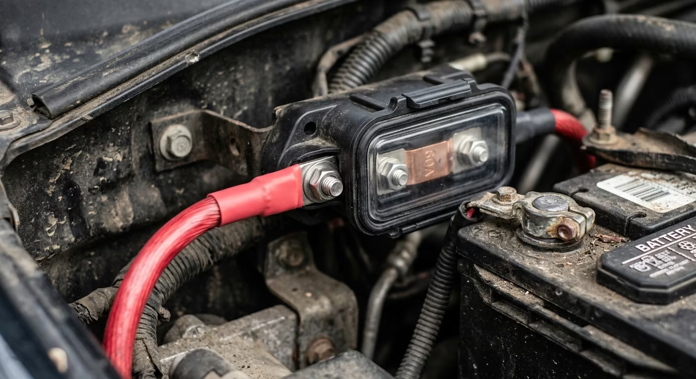
The input line is energized by the engine alternator and starter battery, while the output line is energized by the house lithium battery. If a cable pinches against a sharp metal rib in the center of the vehicle chassis, current will flow into the fault from both directions simultaneously.
Per ABYC E-11.10.1 and ISO standards, you must install overcurrent protection within 7 inches of conductor connection to each power source:
- Input Fuse: Sized for the cable’s maximum ampacity (typically 70A to 90A for a 50A/60A charger), placed within 7 inches of the starter battery positive terminal.
- Output Fuse: Sized for the charger’s rated output plus 20% (typically 50A to 80A), placed within 7 inches of the house battery positive terminal or main DC busbar.
Frequently Asked Questions
Q: Why does my 50A DC-DC charger cycle on and off while driving?
A: This is almost always caused by voltage drop on an undersized input feeder wire. When the charger turns on and pulls 60A+, the resistance of thin wire drops the voltage at the charger input terminals below its low-voltage cut-off threshold (typically 12.0V or 12.2V). The charger shuts off, the voltage instantly rebounds, and the charger restarts—creating an endless cycling loop. Upsizing to 4 AWG or 2 AWG resolves the issue.
Q: Does the wire from the charger to the house battery need to be the same size as the input wire?
A: Not necessarily. If the DC-DC charger is mounted right next to the house battery bank (e.g., within 2 to 3 feet), the output circuit length is very short. A short run of 6 AWG or 4 AWG wire can carry the output current with negligible voltage drop, even if the 20-foot input feeder run requires 2 AWG.
Securing Your Electrical Conduits & Cables?
Keep your electrical installations neat and code-compliant. Check out our parametric conduit clamps and cable organizers, custom-engineered and 3D printed in rugged industrial PETG.