

Wire Sizing for Marine Anchor Windlass Motors (12V/24V High-Amp Loads)
Aside from a bow thruster or a main engine starter, an anchor windlass represents the most intense intermittent direct current (DC) load on a vessel. A standard 1000W electric windlass operating on a 12-volt system routinely draws between 80 and 120 continuous amps under load, with momentary “locked-rotor” surges spiking over 150 amps when breaking out a stubborn anchor from deep mud. Because the battery bank is often located in the engine room at the stern, pushing 120 amps over a 30-foot run to the bow creates a severe thermal bottleneck.
Undersizing the massive copper conductors required for this run results in crippling voltage drop, sluggish retrieval speeds, and extreme heat generation that can literally melt marine insulation. Properly sizing windlass wiring requires navigating the American Boat and Yacht Council (ABYC) E-11 standards, specifically balancing the 10% non-critical voltage drop limit against the sheer physical ampacity requirements of UL 1426 tinned marine copper.
Need Exact Wire Sizing for Your Windlass Run?
Input your windlass motor’s max continuous amperage and the total round-trip distance to instantly calculate the ABYC-compliant AWG.
In This Guide:
ABYC E-11 Voltage Drop Rules for Intermittent Loads
Under the ABYC E-11 standard, marine circuits are divided into critical and non-critical loads. While navigation lights and bilge pumps are restricted to a strict 3% voltage drop, electric windlasses are legally classified as “non-critical” intermittent loads. This means they are permitted to experience a maximum voltage drop of 10%.
However, allowing a full 10% drop on a 12V system means you are sacrificing 1.2 Volts to thermal heat within the cable. If your battery drops to 12.0V under heavy load, the windlass motor is only receiving 10.8V at the bow. This forces the motor to draw even more amperage to compensate, generating excess heat in the motor windings. While 10% is legal, many marine riggers size their conductors closer to a 5% drop to ensure maximum torque and retrieval speed during heavy sea states.
Calculating Circular Mils for High-Amp DC Surges
To mathematically determine the exact conductor thickness required to support 100+ amps, marine engineers utilize the Circular Mils (CM) formula. In all DC applications, distance (L) must be calculated as the Total Round-Trip Distance (from the battery, to the windlass solenoid, and back to the negative busbar).
CM = (10.75 × I × L) / ΔV
Where:
- 10.75: The resistivity constant ($K$) for copper at standard temperature.
- I: The continuous rated current drawn by the windlass (e.g., 100 Amps).
- L: The total round-trip circuit distance in feet (e.g., a 25 ft run = 50 ft total).
- ΔV: The allowable voltage drop ($12text{V} times 0.10 = 1.2text{V}$).
Example Calculation: A 1000W 12V windlass drawing 100 Amps is located 25 feet from the battery (50 feet round-trip).
CM = (10.75 × 100A × 50ft) / 1.2VCM = 53,750 / 1.2 = 44,791 Circular Mils
A 2 AWG cable provides 66,360 CM (plenty of capacity for a 10% drop). However, if you wanted to maintain a strict 5% drop (0.6V) to maximize pulling power, the equation requires 89,583 CM, forcing you to step up to massive 1/0 AWG tinned copper cable.
Sizing Ignition-Protected Circuit Breakers & Solenoids
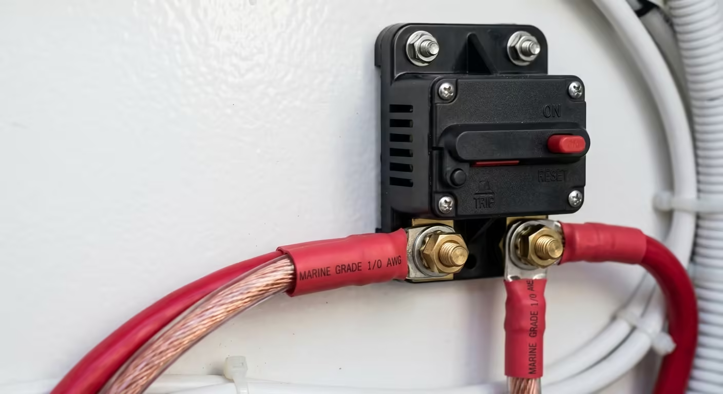
Sizing the overcurrent protection for a windlass requires careful balance. An electric motor pulling an anchor free of thick clay experiences a “locked rotor” event, causing amperage to spike wildly for several seconds. If your breaker is matched identically to the running amps (e.g., a 100A breaker on a 100A motor), it will nuisance-trip constantly.
Manufacturers generally specify a thermal circuit breaker rated roughly 1.3x to 1.5x the continuous running amperage (e.g., a 135A to 150A breaker for a 100A motor). The breaker protects the massive 2 AWG or 1/0 AWG conductor from a dead-short fire, while its “slow-blow” thermal nature allows the momentary anchor-breakout surge to pass without tripping.
Important Note: Because this breaker is located near the battery bank (often in the engine room), it MUST be marked as “Ignition Protected” (SAE J1171) to prevent a stray spark from igniting gas fumes.
12V & 24V Windlass Cable Sizing Matrix
The table below provides minimum recommended Class K Tinned Copper AWG sizes targeting a safe 10% voltage drop across standard hull lengths. (Distances listed are One-Way from battery to bow; the formula accounts for the round trip).
| Motor Wattage / Voltage | Approx. Cont. Amps | 20 ft One-Way Run | 30 ft One-Way Run | 40 ft One-Way Run |
|---|---|---|---|---|
| 700W (12V DC) | 65 Amps | 4 AWG | 2 AWG | 1 AWG |
| 1000W (12V DC) | 95 Amps | 2 AWG | 1/0 AWG | 2/0 AWG |
| 1500W (12V DC) | 135 Amps | 1/0 AWG | 2/0 AWG | 3/0 AWG |
| 1000W (24V DC) | 45 Amps | 8 AWG | 6 AWG | 4 AWG |
| 1500W (24V DC) | 65 Amps | 6 AWG | 4 AWG | 2 AWG |
*Note: Stepping up to a 24V windlass system on larger vessels is highly advantageous. Because doubling the voltage halves the required amperage, you can achieve identical pulling power using much thinner, cheaper, and easier-to-route conductors (e.g., dropping from thick 1/0 AWG down to standard 6 AWG).
Frequently Asked Questions
Q: Can I install a dedicated 12V battery in the bow just for the windlass to avoid pulling long wires?
A: Yes. Installing a dedicated AGM or Lithium battery in the bow eliminates the massive 1/0 AWG wire run entirely. You can use short 2 AWG jumpers from the bow battery to the windlass, and run a much smaller wire (e.g., 10 AWG or 8 AWG) from your stern alternator/charger to slowly recharge the bow battery.
Q: Can I use standard welding cable for my windlass run since it is highly flexible?
A: It depends. Standard welding cable features fine stranding but is often constructed of bare copper, which oxidizes rapidly in a wet marine bilge, causing high resistance. If you use welding cable, it must be specifically marked as UL 1426 Marine Grade Tinned Copper to comply with ABYC standards and resist saltwater corrosion.
Q: How do I terminate massive 1/0 AWG or 2/0 AWG cables at the reversing solenoid?
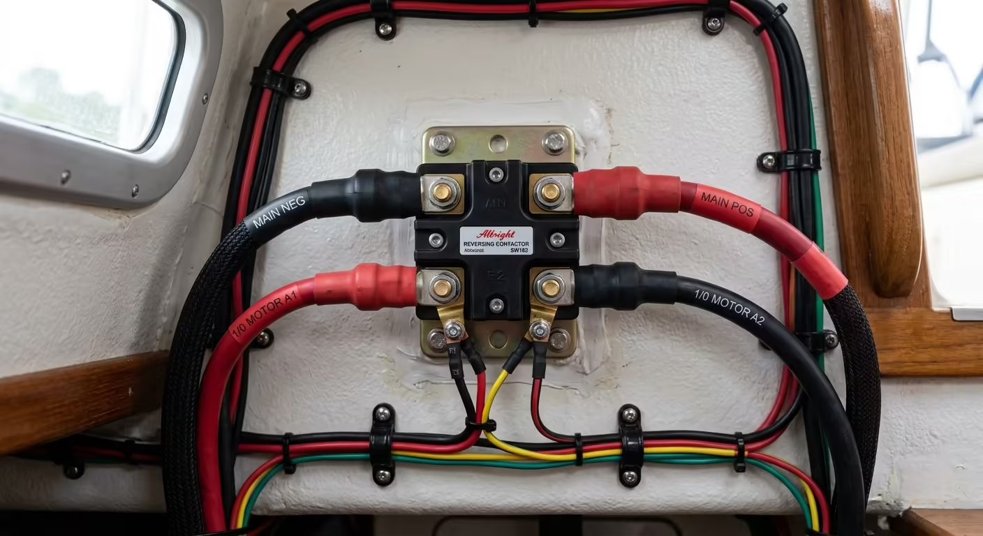
A: Fine-strand Class K marine wire cannot be clamped directly under set screws. You must use a calibrated hydraulic hex crimping tool to compress heavy-duty tinned copper closed-end ring lugs onto the cable, followed by marine-grade adhesive-lined heat shrink to permanently seal the joint against moisture.
Securing Your Marine Cables?
Keep your hull wiring neat, secure, and ABYC compliant. Check out our parametric conduit clamps and marine cable organizers, custom-engineered and 3D printed in rugged industrial PETG.
