

Wire Sizing for Critical Marine Bilge Pump Circuits (12V/24V ABYC Standards)
In the marine environment, the bilge pump is not an optional accessory—it is the final line of defense against catastrophic vessel flooding. However, a high-capacity 2000 GPH (gallons per hour) bilge pump is entirely useless if the conductors powering it suffer from severe voltage drop. Because DC electrical systems push massive amperage at low voltages (12V or 24V), pushing current from the battery bank at the stern to a forward bilge pump can result in thermal losses that drastically reduce the pump’s RPMs, cutting its actual water-clearing volume by over 40%.
To ensure life-safety equipment functions flawlessly under emergency conditions, the American Boat and Yacht Council (ABYC) strictly classifies bilge pumps as “Critical Circuits.” Sizing conductors for these circuits requires abandoning standard 10% non-critical voltage drop limits and adhering strictly to the ABYC E-11 maximum 3% voltage drop rule. Furthermore, system designers must account for locked-rotor surge currents and specify marine-grade tinned copper conductors to survive highly corrosive saltwater submersion zones.
Need Exact Wire Sizing for Your DC Run?
Input your bilge pump amperage, total round-trip distance, and select a 3% safety margin to instantly calculate the ABYC-compliant AWG.
In This Guide:
ABYC E-11 Critical Circuit Standards (The 3% Rule)
Under the ABYC E-11 (AC and DC Electrical Systems on Boats) standard, electrical loads are divided into two categories: non-critical (permitting a 10% voltage drop) and critical (restricted to a 3% maximum voltage drop). Critical circuits include bilge blowers, navigation lights, main DC panel feeders, and bilge pumps.
On a nominal 12V system, a 3% drop equates to a maximum allowable loss of just 0.36 Volts. If your battery rests at 12.2V and your wiring is undersized, delivering only 11.0V to the pump motor under load, the motor’s impeller speed slows dramatically, plunging a 2000 GPH pump down to the effective capacity of a 1000 GPH unit during a flooding emergency.
Calculating Circular Mils for Marine DC Circuits
To mathematically determine the exact conductor size required to maintain a 3% voltage drop, marine engineers use the Circular Mils (CM) formula. In DC runs, distance must always be calculated as the Total Round-Trip Distance (from the battery, to the pump, and back to the negative busbar).
CM = (K × I × L) / ΔV
Where:
- K: Resistivity constant for copper (Use 10.75 for standard calculations, or up to 11.1 depending on ambient engine room heat)
- I: Continuous current drawn by the pump (e.g., 12 Amps)
- L: Total round-trip circuit distance in feet (e.g., a 20 ft one-way run = 40 ft total)
- ΔV: Allowable voltage drop (12V × 0.03 = 0.36V)
Example Calculation: A 1500 GPH bilge pump draws 12 Amps on a 12V system. The pump is located 20 feet away from the battery bank (40 feet round-trip).
CM = (10.75 × 12A × 40ft) / 0.36VCM = 5160 / 0.36 = 14,333 Circular Mils
A standard 10 AWG wire has a cross-sectional area of 10,380 CM (too small, resulting in a drop greater than 3%). You must upsize to 8 AWG copper (16,510 CM) to safely meet the ABYC critical circuit mandate for this specific run.
Tinned Marine Copper (UL 1426) vs. SAE Automotive Wire
Sizing the correct gauge is only half the engineering equation; the metallurgical structure of the wire is equally vital. Never use SAE (Society of Automotive Engineers) automotive primary wire in a marine bilge.
- Bare Copper Oxidation: Standard automotive or residential copper wire reacts instantly to humid, salty marine environments. The bare copper turns black (cupric oxide) and green (copper carbonate), which creates a high-resistance barrier that destroys conductivity and overheats connections.
- UL 1426 BC-5W2 Tinned Marine Cable: ABYC standards strongly recommend Class K flexible tinned copper wire. During manufacturing, every individual micro-strand of copper is individually coated with a thin layer of tin, making the conductor highly resistant to saltwater corrosion and galvanic degradation.
- Vibration Tolerance: Marine hulls endure brutal harmonic vibration from engines and wave impacts. UL 1426 Type III marine wire utilizes hundreds of ultra-fine strands (Type 3 stranding), making the cable highly flexible and immune to the mechanical work-hardening and fatigue snapping that plagues rigid residential wire.
12V & 24V Bilge Pump Sizing Matrix
The table below provides minimum recommended AWG conductor sizes targeting a 3% maximum voltage drop across common 12V and 24V marine bilge pump capacities.
| Pump Capacity / Voltage | Nominal Amp Draw | 10 ft One-Way Run | 20 ft One-Way Run | 30 ft One-Way Run |
|---|---|---|---|---|
| 1000 GPH (12V DC) | 3.5 Amps | 16 AWG | 14 AWG | 12 AWG |
| 1500 GPH (12V DC) | 12.0 Amps | 12 AWG | 8 AWG | 6 AWG |
| 2000 GPH (12V DC) | 16.0 Amps | 10 AWG | 6 AWG | 4 AWG |
| 2000 GPH (24V DC) | 8.0 Amps | 16 AWG | 12 AWG | 10 AWG |
| 4000 GPH (24V DC) | 15.0 Amps | 12 AWG | 10 AWG | 8 AWG |
*Note: This table assumes a 3% voltage drop allowance. Always refer to your specific pump manufacturer’s data sheet for exact nominal amperage and locked-rotor surge requirements.
Frequently Asked Questions
Q: Can I use standard twist-on wire nuts to connect my bilge pump?
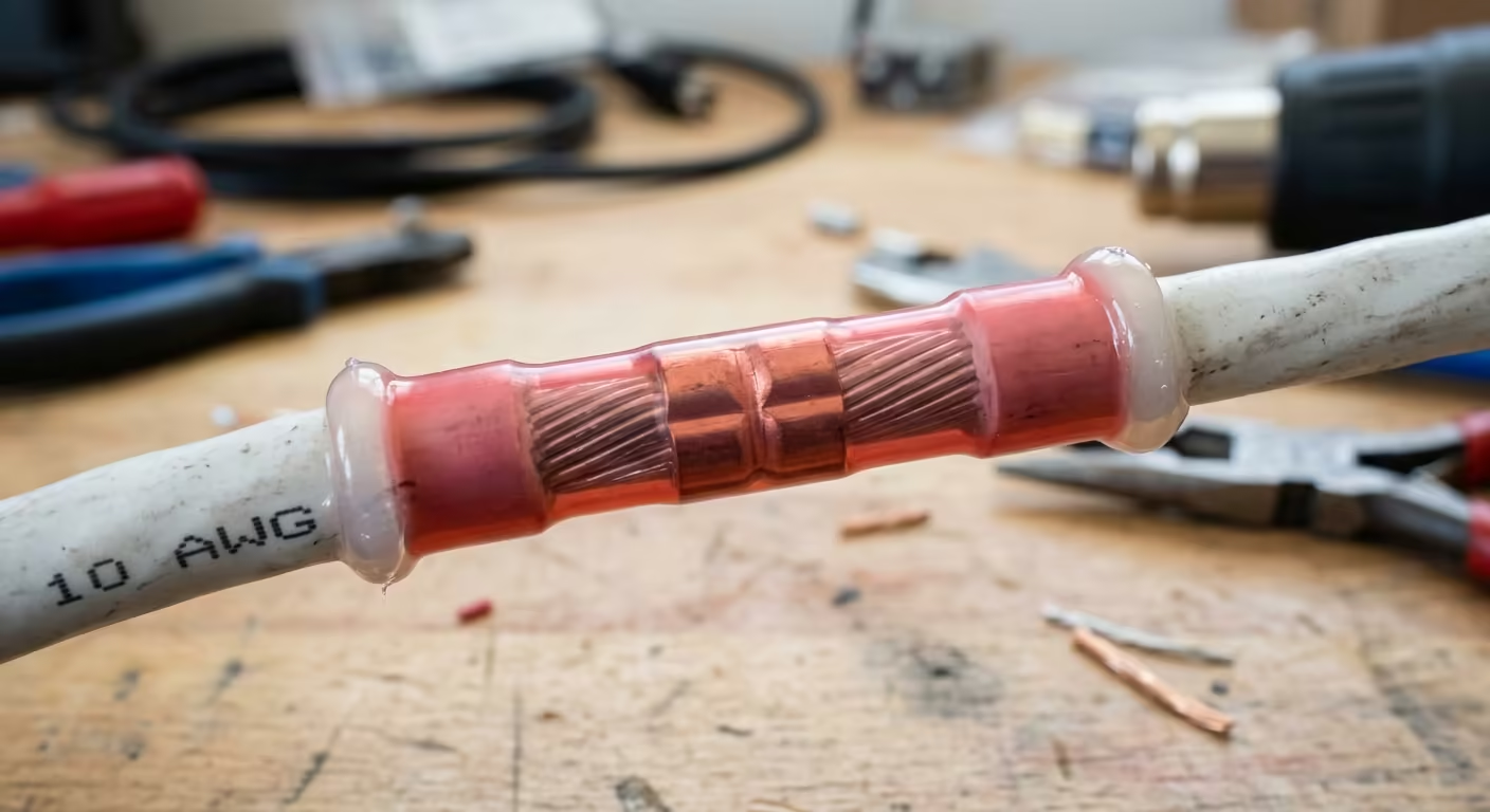
A: No. Standard residential wire nuts trap moisture and are prone to vibrating loose in marine environments. ABYC standards prohibit wire nuts on vessels. You must use adhesive-lined marine heat shrink butt connectors to create a mechanically secure, waterproof seal.
Q: Does a bilge pump need to be wired through the main battery disconnect switch?
A: No. Bilge pumps equipped with automatic float switches must be wired directly to the “always-on” side of the battery (or to a dedicated unswitched 24-hour busbar) with their own dedicated in-line fuse. This ensures the pump remains operational to protect the vessel even when the main master battery switch is turned off.
Q: What size fuse do I need for a 2000 GPH bilge pump?
A: Fuses protect the wire, not the appliance. The fuse must be sized according to the pump manufacturer’s specification to handle momentary starting surges (often 1.5x to 2x the running amps), while remaining lower than the maximum ampacity rating of the wire gauge installed. A 2000 GPH 12V pump drawing 16A typically requires a 20A or 25A ATO/ATC blade fuse located within 7 inches of the battery connection.
Securing Your Electrical Conduits & Cables?
Keep your electrical installations neat and code-compliant. Check out our parametric conduit clamps and cable organizers, custom-engineered and 3D printed in rugged industrial PETG.
