

Sizing Wire from Rooftop Solar Panels to MPPT Charge Controller
Harvesting peak kilowatt-hours from a rooftop solar photovoltaic (PV) array depends on conductor sizing. While many installers focus on module efficiency and panel wattages, undersized DC wiring running from the roof to the Maximum Power Point Tracking (MPPT) charge controller creates a resistive bottleneck. In direct current (DC) circuits, this resistance causes voltage drop, bleeding away usable solar energy as heat before it ever reaches your battery bank or hybrid inverter.
Because photovoltaic modules operate as current-limited power sources subject to full-sun thermal extremes, standard residential sizing practices cannot be used. Sizing conductors between the PV modules and the MPPT controller requires navigating National Electrical Code (NEC) Article 690 rules, calculating continuous load margins (125% factor on short-circuit current), applying ambient rooftop temperature correction factors, and determining whether a series or parallel string layout best controls voltage drop.
Calculating Solar DC Wire Size & Voltage Drop?
Input your string voltage, short-circuit current (Isc), one-way distance, and allowable voltage drop to compute the exact AWG gauge needed.
In This Guide:
NEC 690.8: Determining Maximum Circuit Current (Isc × 1.25)
Under NEC Section 690.8(A)(1), the maximum current for a photovoltaic source circuit is not based on normal operating current ($I_{mp}$), but on the module’s rated short-circuit current ($I_{sc}$) multiplied by an irradiancy safety factor of 125%:
Maximum Circuit Current = Isc × 1.25
This 1.25 factor accounts for atmospheric lensing, snow reflection, and edge-of-cloud effects where irradiance temporarily spikes above Standard Test Conditions ($1000text{ W/m}^2$).
Furthermore, because solar systems operate continuously during daylight hours (defined by NEC Article 100 as 3 hours or more), NEC Section 690.8(B) requires an additional continuous duty multiplier of 125% on top of the maximum circuit current when sizing overcurrent protective devices (OCPD) and uncorrected conductors:
Minimum Conductor Sizing Rating = Isc × 1.25 × 1.25 = Isc × 1.56
For example, a string of modern 400W panels with an $I_{sc}$ of 13.5A requires an ungrounded conductor rated for at least $13.5text{A} times 1.56 = 21.06text{ Amps}$ of allowable ampacity prior to adjustment factors.
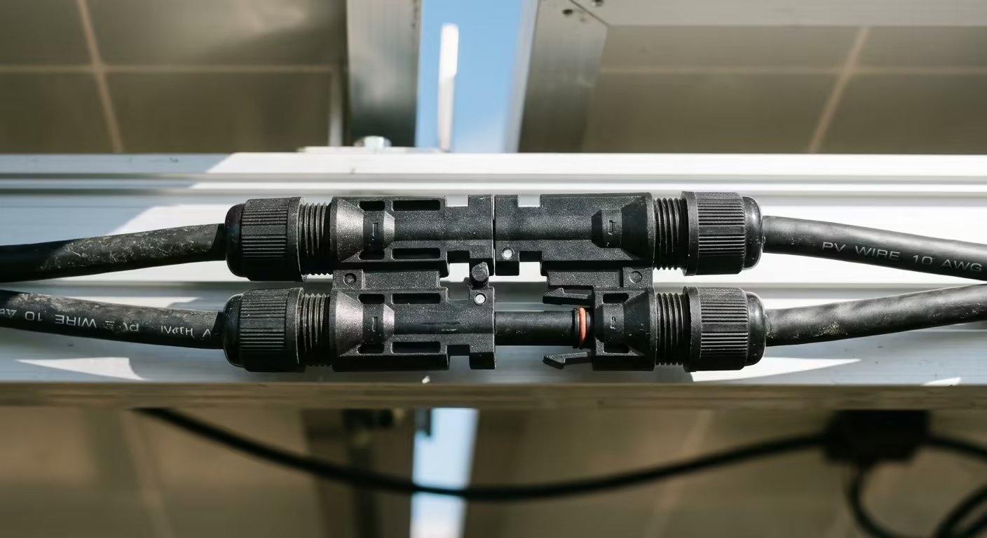
Series vs. Parallel Strings: How Voltage Drop Dictates Gauge
How you arrange your photovoltaic modules directly dictates your conductor diameter. The fundamental rule of DC electricity is that high amperage generates heat, while high voltage transmits efficiently.
The standard single-phase DC voltage drop formula is:
ΔV = (2 × K × I × L) / CM
Where:
- K: Resistivity constant for copper ($12.9text{ ohms-cmil/ft}$ at 75°C)
- I: Circuit current in amperes ($I_{mp}$)
- L: One-way circuit distance in feet
- CM: Conductor cross-sectional area in circular mils (10 AWG = 10,380 CM; 8 AWG = 16,510 CM; 6 AWG = 26,240 CM)
Consider an array of four 400W solar modules ($V_{mp} = 31.0text{V}$, $I_{mp} = 12.9text{A}$) running 75 feet from the roof down to a basement MPPT charge controller:
- Configured in Parallel (31V / 51.6A): Pulling 51.6 amps at 31 volts over 75 feet on standard 10 AWG copper yields an intolerable 9.64V drop (31.1% power loss). Even upsizing to massive 2 AWG copper (66,360 CM) results in a 2.3V drop (7.4% loss), far exceeding the 2% to 3% industry standard.
- Configured in Series (124V / 12.9A): By wiring the four panels in series into an MPPT controller rated for 150V or 250V input, voltage multiplies while current remains at 12.9 amps. Running 12.9A over that same 75-foot distance on standard 10 AWG copper yields a drop of only 2.41V (1.94% drop).
By stepping up the voltage in series, standard 10 AWG or 8 AWG PV wire comfortably keeps voltage drop within the 2% maximum recommended threshold without demanding commercial feeder cable.
Rooftop Conduit Temperature Correction Factors
Solar arrays reside in intense thermal environments. Asphalt shingles and dark metal roofing materials easily hit temperatures of 130°F to 150°F (54°C to 65°C) under direct summer sun. Conductor insulation ampacity drops rapidly as ambient temperatures rise.
All exposed rooftop wiring must utilize UL 4703 listed Photovoltaic (PV) Wire, rated for 90°C wet/dry applications and direct sunlight. When transitioning into conduit (such as EMT or Schedule 80 PVC) on the roof deck, you must apply the temperature correction factors from NEC Table 310.15(B)(1) (or Table 310.16 depending on your local code edition):
| Ambient Temperature Range | 90°C Rating Derating Multiplier | 10 AWG Copper Adjusted Ampacity |
|---|---|---|
| 86°F to 95°F (30°C to 35°C) | 0.96 | 38.4 Amps |
| 105°F to 113°F (41°C to 45°C) | 0.87 | 34.8 Amps |
| 123°F to 131°F (51°C to 55°C) | 0.76 | 30.4 Amps |
| 141°F to 158°F (61°C to 70°C) | 0.58 | 23.2 Amps (Critical Limit) |
While 10 AWG copper has a base rating of 40 amps at 90°C, extreme rooftop heat derates its safe continuous ampacity to roughly 23A. If your parallel combiner output draws more than 20 amps, you must step up to 8 AWG or 6 AWG copper to survive thermal exposure.
Solar PV to MPPT Conductor Sizing Reference Table
The table below provides minimum recommended copper conductor sizes targeting a 2% maximum voltage drop across common residential MPPT string configurations:
| Array Configuration | Nominal Vmp / Imp | 50 ft One-Way | 100 ft One-Way | 150 ft One-Way |
|---|---|---|---|---|
| 2 Panels in Series (800W) | 62V / 13A | 10 AWG (1.3%) | 8 AWG (1.6%) | 6 AWG (1.5%) |
| 4 Panels in Series (1600W) | 124V / 13A | 10 AWG (0.7%) | 10 AWG (1.3%) | 8 AWG (1.2%) |
| 6 Panels in Series (2400W) | 186V / 13A | 10 AWG (0.4%) | 10 AWG (0.9%) | 10 AWG (1.3%) |
| 2 Strings Parallel (3200W) | 124V / 26A | 8 AWG (1.6%) | 6 AWG (2.0%) | 4 AWG (1.6%) |
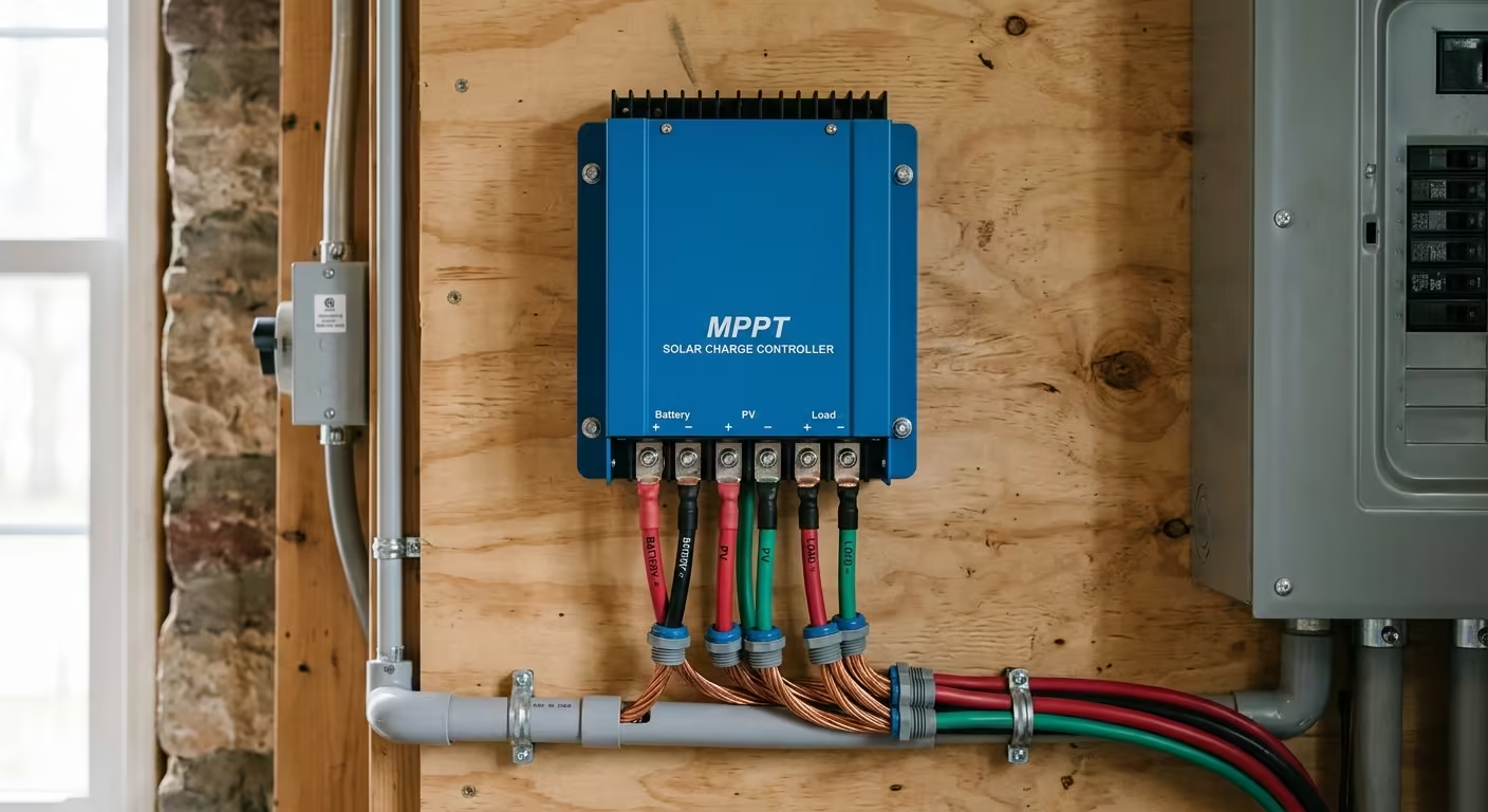
Terminal Constraints: MC4 Pins & MPPT Lug Terminations
Before pulling upsized cable through conduit, verify mechanical terminal constraints at both ends of the run:
- MC4 Connector Boundaries: Standard solar branch connectors are limited to 30 amps and accept a maximum wire size of 10 AWG (some specialized connectors accept 8 AWG). If your distance calculations demand 6 AWG copper, transition inside a rooftop combiner box or NEMA 3R junction box. Terminate your 10 AWG module strings onto a DC terminal block and run 6 AWG feeder conductors down the conduit.
- MPPT Controller Clamps: Residential MPPT controllers (such as Victron SmartSolar or MidNite Solar) typically accept wire sizes up to 6 AWG or 4 AWG directly into their cage clamps. If you pull 2 AWG conductors to satisfy a long voltage drop run, you must install an external DC disconnect switch adjacent to the controller and step down to a short 6 AWG whip.
Frequently Asked Questions
Q: Can I use standard THHN wire for solar panel wiring on the roof?
A: No. Standard THHN wire is not UV-rated, moisture-rated, or certified for exposed outdoor use on rooftops. You must use UL 4703 listed Photovoltaic (PV) Wire for all exposed module interconnects. However, once your PV wire enters a continuous raceway or conduit junction box, you may transition to dual-rated THHN/THWN-2 copper wire for the interior run.
Q: What is the maximum allowable voltage drop for solar PV string wiring?
A: The National Electrical Code recommends a maximum overall voltage drop of 3% across branch circuits, but leading solar engineering standards target a maximum of 1.5% to 2% between the array and the MPPT charge controller. Because lost voltage translates to direct kilowatt-hour loss over a 25-year system lifespan, conservative conductor sizing pays for itself quickly.
Q: Do I need a DC disconnect between my solar panels and the MPPT controller?
A: Yes. Under NEC Section 690.13, a readily accessible DC disconnect switch must be installed in the photovoltaic system circuit to isolate the charge controller or inverter for maintenance without working on live, energized DC conductors.
Q: What size equipment ground wire is required for a solar array?
A: In accordance with NEC 690.45 and NEC Table 250.122, an equipment grounding conductor (EGC) for a rooftop array is typically sized at a minimum of 10 AWG or 8 AWG bare copper, bonded to each panel frame and mounting rail using UL 2703 listed grounding lugs.
Securing Your Electrical Conduits & Cables?
Keep your electrical installations neat and code-compliant. Check out our parametric conduit clamps and cable organizers, custom-engineered and 3D printed in rugged industrial PETG.
